A set of very high-resolution photographs of the Fukushima Dai-Ichi nuclear plant have been posted on the web by cryptome.org. I’ve annotated some of those pictures below to help people know what they are seeing in those photos.
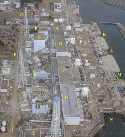
Photo 1: (original photo: Air Photo Service Co. Ltd., Japan)

1A – Unit 1 turbine building containing the main turbine, main generator, condenser, condensate pumps, and condensate booster pumps
1B – Unit 2 turbine building containing the main turbine, main generator, condenser, condensate pumps, and condensate booster pumps
1C – Unit 3 turbine building containing the main turbine, main generator, condenser, condensate pumps, and condensate booster pumps
1D – Unit 4 turbine building containing the main turbine, main generator, condenser, condensate pumps, and condensate booster pumps
1E – Offgas building shared by all four units containing equipment to process air pulled from the condensers and reduce radioactivity discharged from the offgas stack during normal reactor operation
1F – Unit 1 reactor building with extensive damage caused by hydrogen explosion
1G – Unit 2 reactor building
1H – Unit 3 reactor building with extensive damage caused by hydrogen explosion
1I – Unit 4 reactor building with extensive damage caused by hydrogen explosion
1J – Offgas stack discharging treated flow from Units 1-4 during normal operation
1K – Unit 1 intake where sea water is pumped via underground pipes into the condenser within the Unit 1 turbine building (A) to cool the steam exiting the main turbine. The warmed sea water flows through underground pipe to a common concrete culvert to the discharge point (N).
1L – Unit 2 intake where sea water is pumped via underground pipes into the condenser within the Unit 1 turbine building (B) to cool the steam exiting the main turbine. The warmed sea water flows through underground pipe to a common concrete culvert to the discharge point (N).
1M – Unit 3 intake where sea water is pumped via underground pipes into the condenser within the Unit 1 turbine building (C) to cool the steam exiting the main turbine. The warmed sea water flows through underground pipe to a common concrete culvert to the discharge point (N).
1N – Common discharge point used by Units 1, 2, 3, and 4 to return warmed sea water to the Pacific Ocean
1O – Stack shared by the Unit 1 and Unit 2 reactor building exhaust system. Air from the reactor buildings is discharged from this stack during normal operations. During accident conditions, a system within the reactor building routes air through a charcoal filter system before sending it to the stack for discharge. The primary containment is vented through the reactor building charcoal filter system before flowing through the lines to the stack.
1P – Stack shared by the Unit 3 and Unit 4 reactor building exhaust system. Air from the reactor buildings is discharged from this stack during normal operations. During accident conditions, a system within the reactor building routes air through a charcoal filter system before sending it to the stack for discharge. The primary containment is vented through the reactor building charcoal filter system before flowing through the lines to the stack.
____________________________________________________________________
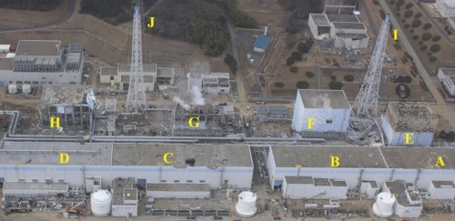
Photo 2: (original photo: Air Photo Service Co. Ltd., Japan)

2A – Unit 1 turbine building containing the main turbine, main generator, condenser, condensate pumps, and condensate booster pumps
2B – Unit 2 turbine building containing the main turbine, main generator, condenser, condensate pumps, and condensate booster pumps
2C – Unit 3 turbine building containing the main turbine, main generator, condenser, condensate pumps, and condensate booster pumps
2D – Unit 4 turbine building containing the main turbine, main generator, condenser, condensate pumps, and condensate booster pumps
2E – Unit 1 reactor building with extensive damage caused by hydrogen explosion
2F – Unit 2 reactor building showing blow-out panel opened to relief hydrogen and vapor buildups
2G – Unit 3 reactor building with extensive damage caused by hydrogen explosion
2H – Unit 4 reactor building with extensive damage caused by hydrogen explosion
2I – Stack shared by the Unit 1 and Unit 2 reactor building exhaust system. Air from the reactor buildings is discharged from this stack during normal operations. During accident conditions, a system within the reactor building routes air through a charcoal filter system before sending it to the stack for discharge. The primary containment is vented through the reactor building charcoal filter system before flowing through the lines to the stack.
2J – Stack shared by the Unit 3 and Unit 4 reactor building exhaust system. Air from the reactor buildings is discharged from this stack during normal operations. During accident conditions, a system within the reactor building routes air through a charcoal filter system before sending it to the stack for discharge. The primary containment is vented through the reactor building charcoal filter system before flowing through the lines to the stack.
____________________________________________________________________
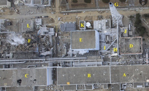
Photo 3: (original photo: Air Photo Service Co. Ltd., Japan)

3A – Unit 1 turbine building containing the main turbine, main generator, condenser, condensate pumps, and condensate booster pumps
3B – Unit 2 turbine building containing the main turbine, main generator, condenser, condensate pumps, and condensate booster pumps
3C – Unit 3 turbine building containing the main turbine, main generator, condenser, condensate pumps, and condensate booster pumps
3D – Unit 1 reactor building with extensive damage caused by hydrogen explosion
3E – Unit 2 reactor building
3F – Unit 3 reactor building with extensive damage caused by hydrogen explosion
3G – Stack shared by the Unit 1 and Unit 2 reactor building exhaust system. Air from the reactor buildings is discharged from this stack during normal operations. During accident conditions, a system within the reactor building routes air through a charcoal filter system before sending it to the stack for discharge. The primary containment is vented through the reactor building charcoal filter system before flowing through the lines to the stack.
3H – Unit 1 reactor building (D) exhaust line to the stack (G)
3I – Unit 2 reactor building (E) exhaust line to the stack (G)
3J – Unit 1 truck bay used to deliver canisters of new fuel assemblies into the reactor building (D) and its refueling floor
3K – Unit 2 truck bay used to deliver canisters of new fuel assemblies into the reactor building (D) and its refueling floor
3L – Unit 3 truck bay used to deliver canisters of new fuel assemblies into the reactor building (D) and its refueling floor
_____________________________________________________________________
Photo 4: (original photo: Air Photo Service Co. Ltd., Japan)

4A – Unit 2 turbine building containing the main turbine, main generator, condenser, condensate pumps, and condensate booster pumps
4B – Unit 3 turbine building containing the main turbine, main generator, condenser, condensate pumps, and condensate booster pumps
4C – Unit 4 turbine building containing the main turbine, main generator, condenser, condensate pumps, and condensate booster pumps
4D – Unit 3 reactor building with extensive damage caused by hydrogen explosion
4E – Unit 4 reactor building with extensive damage caused by hydrogen explosion
4F – Unit 3 reactor building (D) exhaust line to the stack (H) showing extensive damage
4G – Unit 4 reactor building (E) exhaust line to the stack (H)
4H – Stack shared by the Unit 3 and Unit 4 reactor building exhaust system. Air from the reactor buildings is discharged from this stack during normal operations. During accident conditions, a system within the reactor building routes air through a charcoal filter system before sending it to the stack for discharge. The primary containment is vented through the reactor building charcoal filter system before flowing through the lines to the stack.
4I – Offgas building shared by all four units containing equipment to process air pulled from the condensers and reduce radioactivity discharged from the offgas stack during normal reactor operation
4J – Offgas stack discharging treated flow from Units 1-4 during normal operation
Additional annotated photos are posted here.
