The Florida Power & Light Company’s Turkey Point Nuclear Generating Station about 20 miles south of Miami has two Westinghouse pressurized water reactors that began operating in the early 1970s. Built next to two fossil-fired generating units, Units 3 and 4 each add about 875 megawatts of nuclear-generated electricity to the power grid.
Both reactors hummed along at full power on the morning of Saturday, March 18, 2017, when problems arose.
The Event
At 11:07 am, a high energy arc flash (HEAF) in Cubicle 3AA06 of safety-related Bus 3A ignited a fire and caused an explosion. The explosion inside the small concrete-wall room (called Switchgear Room 3A) injured a worker and blew open Fire Door D070-3 into the adjacent room housing the safety-related Bus 3B (called Switchgear Room 3B.)
A second later, the Unit 3 reactor automatically tripped when Reactor Coolant Pump 3A stopped running. This motor-driven pump received its electrical power from Bus 3A. The HEAF event damaged Bus 3A, causing the reactor coolant pump to trip on under-voltage (i.e., less than the desired voltage of 4,160 volts.) The pump’s trip triggered the insertion of all control rods into the reactor core, terminating the nuclear chain reaction.
Another second later and Reactor Coolant Pumps 3B and 3C also stopped running. These motor-driven pumps received electricity from Bus 3B. The HEAF event should have been isolated to the Switchgear Room 3A, but the force of the explosion blew open the connecting fire door, allowing Bus 3B to also be affected. Reactor Coolant Pumps 3B and 3C tripped on under-frequency (i.e., alternating current electricity at too much less than the desired 60 cycles per second). Each Turkey Point unit has three Reactor Coolant Pumps that force the flow of water through the reactor core, out the reactor vessel to the steam generators where heat gets transferred to a secondary loop of water, and then back to the reactor vessel. With all three pumps turned off, the reactor core would be cooled by natural circulation. Natural circulation can remove small amounts of heat, but not larger amounts; hence, the reactor automatically shuts down when even one of its three Reactor Coolant Pumps is not running.
At shortly before 11:09 am, the operators in the control room received word about a fire in Switchgear Room 3A and the injured worker. The operators dispatched the plant’s fire brigade to the area. At 11:19 am, the operators declared an emergency due to a “Fire or Explosion Affecting the Operability of Plant Systems Required to Establish or Maintain Safe Shutdown.”
At 11:30 am, the fire brigade reported to the control room operators that there was no fire in either Switchgear Room 3A or 3B.
Complication #1
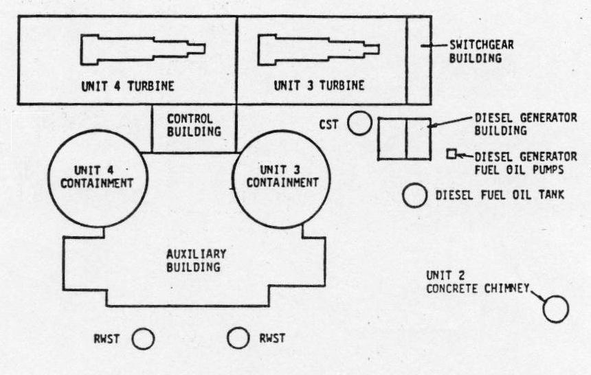
The Switchgear Building is shown on the right end of the Unit 3 turbine building. Switchgear Rooms 3A and 3B are located adjacent to each other within the Switchgear Building. The safety-related buses inside these rooms take 4,160 volt electricity from the main generator, the offsite power grid, or an EDG and supply it to safety equipment needed to protect workers and the public from transients and accidents. Buses 3A and 3B are fully redundant; either can power enough safety equipment to mitigate accidents.

Fig. 1 (Source: Nuclear Regulatory Commission)
To guard against a single file disabling both Bus 3A and Bus 3B despite their proximity, each switchgear room is designed as a 3-hour fire barrier. The floor, walls, and ceiling of the room are made from reinforced concrete. The opening between the rooms has a normally closed door with a 3-hour fire resistance rating.
Current regulatory requirements do not require the room to have blast resistant fire doors, unless the doors are within 3 feet of a potential explosive hazard. (I could give you three guesses why all the values are 3’s, but a correct guess would divulge one-third of nuclear power’s secrets.) Cubicle 3AA06 that experienced the HEAF event was 14.5 feet from the door.
Fire Door D070-3, presumably unaware that it was well outside the 3-feet danger zone, was blown open by the HEAF event. The opened door created the potential for one fire to disable Buses 3A and 3B, plunging the site into a station blackout. Fukushima reminded the world why it is best to stay out of the station blackout pool.
Complication #2
The HEAF event activated all eleven fire detectors in Switchgear Room 3A and activated both of the very early warning fire detectors in Switchgear Room 3B. Activation of these detectors sounded alarms at Fire Alarm Control Panel 3C286, which the operators acknowledged. These detectors comprise part of the plant’s fire detection and suppression systems intended to extinguish fires before they cause enough damage to undermine nuclear safety margins.
But workers failed to reset the detectors and restore them to service until 62 hours later. Bus 3B provided the only source of electricity to safety equipment after Bus 3A was damaged by the HEAF event. The plant’s fire protection program required that Switchgear Room 3B be protected by the full array of fire detectors or by a continuous fire watch (i.e., workers assigned to the area to immediately report signs of smoke or fire to the control room.) The fire detectors were out-of-service for 62 hours after the HEAF event and the continuous fire watches were put in place late.
Workers were in Switchgear Room 3B for nearly four hours after the HEAF event performing tasks like smoke removal. But a continuous fire watch was not posted after they left the area until 1:15 pm on March 19, the day following the HEAF event. And these workers were placed in Switchgear Room 3A, not in Switchgear Room 3B housing the bus that needed to be protected.
Had a fire started in Switchgear Room 3B, neither the installed fire detectors nor the human fire detectors would have alerted control room operators. The lights going out on Broadway, or whatever they call the main avenue at Turkey Point, might have been their first indication.
Complication #3
At 12:30 pm on March 18, workers informed the control room operators that the HEAF event damaged Bus 3A such that it could not be re-energized until repairs were completed. Bus 3A provided power to Reactor Coolant Pump 3A and to other safety equipment like the ventilation fan for the room containing Emergency Diesel Generator (EDG) 3A. Due to the loss of power to the room’s ventilation fan, the operators immediately declared EDG 3A inoperable.
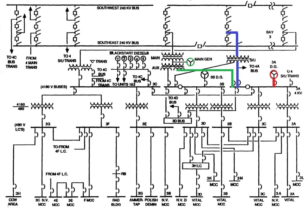
EDGs 3A and 3B are the onsite backup sources of electrical power for safety equipment. When the reactor is operating, the equipment is powered by electricity produced by the main generator as shown by the green line in Figure 2. When the reactor is not operating, electricity from the offsite power grid flows in through transformers and Bus 3A to the equipment as indicated by the blue line in Figure 2. When under-voltage or under-frequency is detected on their respective bus, EDG 3A and 3B will automatically start and connect to the bus to supply electricity for the equipment as shown by the red line in Figure 2.

Fig. 2 (Source: Nuclear Regulatory Commission with colors added by UCS)
Very shortly after the HEAF event, EDG 3A automatically started due to under-voltage on Bus 3A. But protective relays detected a fault on Bus 3A and prevented electrical breakers from closing to connect EDG 3A to Bus 3A. EDG 3A was operating, but disconnected from Bus 3A, when the operators declared it inoperable at 12:30 pm due to loss of the ventilation fan for its room.
But the operators allowed “inoperable” EDG 3A to continue operating until 1:32 pm. Given that (a) its ventilation fan was not functioning, and (b) it was not even connected to Bus 3A, they should not have permitted this inoperable EDG from operating for over an hour.
Complication #4
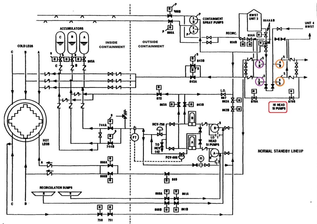
A few hours before the HEAF event on Unit 3, workers removed High Head Safety Injection (HHSI) pumps 4A and 4B from service for maintenance. The HHSI pumps are designed to transfer makeup water from the Refueling Water Storage Tank (RWST) to the reactor vessel during accidents that drain cooling water from the vessel. Each unit has two HHSI pumps; only one HHSI pump needs to function in order to provide adequate reactor cooling until the pressure inside the reactor vessel drops low enough to permit the Low Head Safety Injection pumps to take over.
On the day before, workers found a small leak from a small test line downstream of the common pipe for the recirculation lines of HHSI Pumps 4A and 4B (circled in orange in Figure 3). The repair work was estimated to take 18 hours. Both pumps had to be isolated in order for workers to repair the leaking section.
Pipes cross-connect the HHSI systems for Units 3 and 4 such that HHSI Pumps 3A and 3B (circled in purple in Figure 3) could supply makeup cooling water to the Unit 4 reactor vessel when HHSI Pumps 4A and 4B were removed from service. The operating license allowed Unit 4 to continue running for up to 72 hours in this configuration.

Fig. 3 (Source: Nuclear Regulatory Commission with colors added by UCS)
Before removing HHSI Pumps 4A and 4B from service, operators took steps to protect HHSI Pumps 3A and 3B by further restricting access to the rooms housing them and posting caution signs at the electrical breakers supplying electricity to these motor-driven pumps.
But operators did not protect Buses 3A and 3B that provide power to HHSI Pumps 3A and 3B respectively. Instead, they authorized work to be performed in Switchgear Room 3A that caused the HEAF event.
The owner uses a computer program to characterize risk of actual and proposed plant operating configurations. Workers can enter components that are broken and/or out of service for maintenance and the program bins the associated risk into one of three color bands: green, yellow, and red in order of increasing risk. With only HHSI Pumps 4A and 4B out of service, the program determined the risk for Units 3 and 4 to be in the green range. After the HEAF event disabled HHSI Pump 3A, the program determined that the risk for Unit 4 increased to nearly the green/yellow threshold while the risk for Unit 3 moved solidly into the red band.
The Cause(s)
On the morning of Saturday, March 18, 2017, workers were wrapping a fire-retardant material called Thermo-Lag around electrical cabling in the room housing Bus 3A. Meshing made from carbon fibers was installed to connect sections of Thermal-Lag around the cabling for a tight fit. To minimize the amount of debris created in the room, workers cut the Thermal-Lag material to the desired lengths at a location outside the room about 15 feet away. But they cut and trimmed the carbon fiber mesh to size inside the room.
Bus 3A is essentially the nuclear-sized equivalent of a home’s breaker panel. Open the panel and one can open a breaker to stop the flow of electricity through that electrical circuit within the house. Bus 3A is a large metal cabinet. The cabinet is made up of many cubicles housing the electrical breakers controlling the supply of electricity to the bus and the flow of electricity to components powered by the bus. Because energized electrical cables and components emit heat, the metal doors of the cubicles often have louvers to let hot air escape.
The louvers also allow dust and small airborne debris (like pieces of carbon fiber) to enter the cubicles. The violence of the HEAF event (a.k.a. the explosion) destroyed some of the evidence at the scene, but carbon fiber pieces were found inside the cubicle where the HEAF occurred. The carbon fiber was conductive, meaning that it could transport electrical current. Carbon fiber pieces inside the cubicle, according to the NRC, “may have played a significant factor in the resulting bus failure.”
Further evidence inside the cubicle revealed that the bolts for the connection of the “C” phase to the bottom of the panel had been installed backwards. These backwards bolts were the spot where high-energy electrical current flashed over, or arced, to the metal cabinet.
As odd as it seems, installing fire retardant materials intended to lessen the chances that a single fire compromises both electrical safety systems started a fire that compromised both electrical safety systems.
The Precursor Events (and LEAF)
On February 2, 2017, three electrical breakers unexpectedly tripped open while workers were cleaning up after removing and replacing thermal insulation in the new electrical equipment room.
On February 8, 2017, “A loud bang and possible flash were reported to have occurred” in the new electrical equipment room as workers were cutting and installing Thermo-Lag. Two electrical breakers unexpectedly tripped open. The equipment involved used 480 volts or less, making this a low energy arc fault (LEAF) event.
NRC Sanctions
The NRC dispatched a special inspection team to investigate the causes and corrective actions of this HEAF event. The NRC team identified the following apparent violations of regulatory requirements that the agency is processing to determine the associated severity levels of any applicable sanctions:
- Failure to establish proper fire detection capability in the area following the HEAF event.
- Failure to properly manage risk by allowing HHSI Pumps 4A and 4B to be removed from service and then allowing work inside the room housing Bus 3A.
- Failure to implement effective Foreign Material Exclusion measures inside the room housing Bus 3A that enabled conductive particles to enter energized cubicles.
- Failure to provide adequate design control in that equipment installed inside Cubicle 3AA06 did not conform to vendor drawings or engineering calculations.
UCS Perspective
This event illustrates both the lessons learned and the lessons unlearned from the fire at the Browns Ferry Nuclear Plant in Alabama that happened almost exactly 42 years earlier. The lesson learned was that a single fire could disable primary safety systems and their backups.
The NRC adopted regulations in 1980 intended to lessen the chances that one fire could wreak so much damage. The NRC found in the late 1990s that most of the nation’s nuclear power reactors, including those at Browns Ferry, did not comply with these fire protection regulations. The NRC amended its regulations in 2004 giving plant owners an alternative means for managing the fire hazard risk. Workers were installing fire protection devices at Turkey Point in March 2017 seeking to achieve compliance with the 2004 regulations because the plant never complied with the 1980 regulations.
The unlearned lesson involved sheer and utter failures to take steps after small miscues to prevent a bigger miscue from happening. The fire at Browns Ferry was started by a worker using a lit candle to check for air leaking around sealed wall penetrations. The candle’s flame ignited the highly flammable sealant material. The fire ultimately damaged cables for all the emergency core cooling systems on Unit 1and most of those systems on Unit 2. Candles had routinely been used at Browns Ferry and other nuclear power plants to check for air leaks. Small fires had been started, but had always been extinguished before causing much damage. So, the unsafe and unsound practice was continued until it very nearly caused two reactors to meltdown. Then and only then did the nuclear industry change to a method that did not stick open flames next to highly flammable materials to see if air flow caused the flames to flicker.
Workers at Turkey Point were installing fire retardant materials around cabling. They cut some material in the vicinity of its application. On two occasions in February 2017, small debris caused electrical breakers to trip open unexpectedly. But they continued the unsafe and unsound practice until it caused a fire and explosion the following month that injured a worker and risked putting the reactor into a station blackout event. Then and only then did the plant owner find a better way to cut and install the material. That must have been one of the easiest searches in nuclear history.
The NRC – Ahead of this HEAF Curveball
The NRC and its international regulatory counterparts have been concerned about HEAF events in recent years. During the past two annual Regulatory Information Conferences (RICs), the NRC conducted sessions about fire protection research that covered HEAF. For example, the 2016 RIC included presentations from the Japanese and American regulators about HEAF. These presentations included videos of HEAF events conducted under lab conditions. The 2017 RIC included presentations about HEAF by the German and American regulators. Ironically, the HEAF event at Turkey Point occurred just a few days after the 2017 RIC session.
HEAF events were not fully appreciated when regulations were developed and plants were designed and built. The cooperative international research efforts are defining HEAF events faster than could be accomplished by any country alone. The research is defining factors that affect the chances and consequences of HEAF events. For example, the research indicates that the presence of aluminum, like in cable trays holding the energized electrical cables, can be ignited during a HEAF event, significantly adding to the magnitude and duration of the event.
As HEAF research defined risk factors, the NRC has been working with nuclear industry representatives to better understand the role these factors may play across the US fleet of reactors. For example, the NRC recently obtained a list of aluminum usage around high voltage electrical equipment.
The NRC needs to understand HEAF factors as fully as practical before it can determine if additional measures are needed to manage the risk. The NRC is also collecting information about potential HEAF vulnerabilities. Collectively, these efforts should enable the NRC to identify any nuclear safety problems posed by HEAF events and to implement a triaged plan that resolves the biggest vulnerabilities sooner rather than later.
